Apr 22, 2025
It is named "Globe body" because its internal flow channel design is approximately spherical. Using compressed air as a power source to regulate the flow and velocity of fluids (such as water, steam, gas, oil, etc.), coupled with connected pneumatic actuators, the actuators, upon receiving compressed air signals, push the valve core up and down.
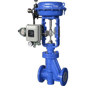
A typical pneumatic globe control valve primarily consists of the following parts:
Valve Body
The valve body is one of the most critical components in the valve structure. It not only withstands internal pressure from the pipeline system but also directly contacts the fluid medium, determining the valve's strength, sealing performance, and fluid compatibility. The valve body serves to house other valve components (such as the plug, seat, and bonnet) and is also the core component for controlling the fluid path and flow characteristics.
Depending on the valve type, the valve body can be designed as straight-through, angle, three-way, or Y-type to accommodate different installation spaces, fluid properties, and control requirements. For example, angle-type valve bodies are suitable for frequent on-off operations, easy drainage, or avoiding liquid accumulation, while Y-type valve bodies reduce flow resistance while maintaining flow velocity, making them more suitable for high-viscosity or particle-laden fluids.
To ensure long-term resistance to high temperatures, high pressure, and corrosive environments, the valve body is typically made of materials with high strength, corrosion resistance, and temperature resistance, such as carbon steel, stainless steel, cast steel, alloy steel, titanium, or special composite materials. Selecting the most suitable material based on specific working conditions is key to ensuring valve longevity and system safety.
Valve Plug
Works in conjunction with the valve seat to control the flow rate. Different shapes (e.g., plunger, conical) are used depending on the application, affecting regulation accuracy.
Valve Seat
Installed inside the valve body, it forms a sealing pair with the valve plug to provide shutoff or throttling functions.
Stem
Connects the valve plug to the actuator, transmitting control signals to move the plug up or down.
Packing/Seals
Prevents medium leakage along the stem.
Pneumatic Actuator
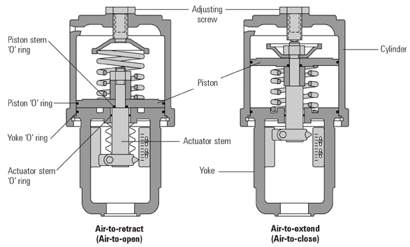
The pneumatic actuator for globe valves typically comes in two forms: piston-type and diaphragm-type. Unlike the rotary motion used in ball and butterfly valve actuators, globe valves employ linear motion.
Piston-Type Pneumatic Actuator
The piston-type pneumatic actuator consists of a piston, cylinder, push rod, spring, sealing rings, guide rings, and inlet/exhaust ports. Its working principle is similar to that of a cylinder. The piston actuator uses compressed air to push the piston back and forth within the cylinder, generating linear thrust to push or pull the valve stem, thereby achieving valve opening, closing, or position adjustment.
Piston actuators come in two types: single-acting and double-acting:
Single-acting piston-type: When compressed air enters one side of the actuator, it pushes the piston forward to open the valve. When the air supply is cut off, the spring's counterforce returns the piston to its original position, closing the valve.
Double-acting piston-type: Both directions are controlled by air pressure, eliminating the need for a spring. Suitable for higher thrust requirements. When compressed air enters one side, it pushes the piston forward (e.g., to open the valve), while air is expelled from the other side. To close the valve, air is supplied from the opposite direction, moving the piston in reverse.
Diaphragm-Type Pneumatic Actuator
The diaphragm-type pneumatic actuator is a single-acting mechanism that uses a flexible diaphragm and pressure differential to move the valve stem. Its structure includes a main diaphragm, spring, air chamber, push rod, and housing. It operates primarily through spring force and diaphragm movement, making it widely used in control valves. This type of actuator is cost-effective, simple in structure, and easy to install and operate, especially in automatic control scenarios for small and medium-sized valves.
Pneumatic Valve Positioner
The pneumatic valve positioner is a regulating device installed on the control valve actuator. Its main function is to accurately control the valve opening based on control signals from systems like DCS or PLC, improving the valve's response speed, control accuracy, and stability.
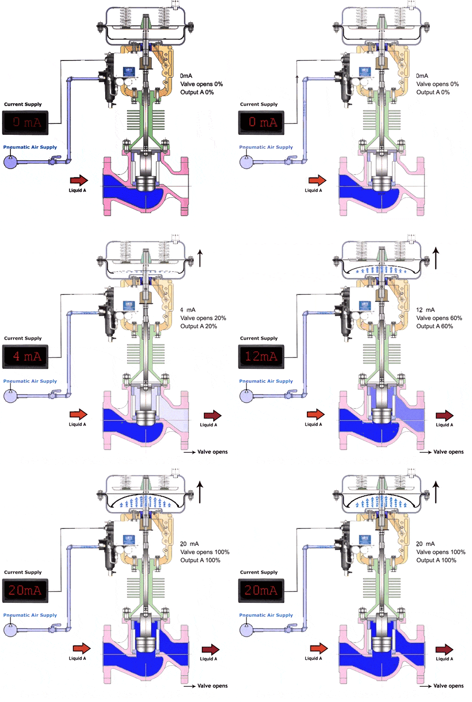
In simple terms, when the control system sends a control signal, the valve positioner converts it into corresponding air pressure to drive the pneumatic actuator. This moves the valve plug up or down, changing the opening between the plug and seat to regulate the fluid flow rate.
Valve Closing Cycle
When the control system or solenoid valve supplies compressed air to the pneumatic actuator, the air enters the actuator's air chamber, generating sufficient pressure to overcome the spring force and push the piston (or diaphragm) downward along the valve axis. As the piston moves, the valve plug or disc is pressed against the seat, achieving complete valve closure. At this point, the fluid passage is fully blocked, preventing medium flow.
Valve Opening Cycle
When the solenoid valve switches states, cutting off the air supply and releasing internal pressure, the compressed air is expelled through the exhaust port, rapidly reducing the air chamber pressure. The spring force then pushes the piston or diaphragm in the opposite direction, pulling the valve stem upward. As the plug moves away from the seat, the fluid passage gradually opens, eventually reaching full valve opening, allowing free fluid flow.
Regulation Cycle
In regulating conditions, the pneumatic actuator does not move the piston to its full stroke limit. The control signal applies partial air pressure based on actual process requirements, positioning the actuator at an intermediate point. This results in partial valve opening or closing, adjusting the valve opening to precisely control medium flow, pressure, or temperature. This process is a dynamic, continuous regulation cycle coordinated by control components like the valve positioner, ensuring rapid response and precise control.
Pneumatic control globe valves offer rapid response, precise control, excellent sealing, and safety, making them ideal for high-temperature, high-pressure industrial automation fluid control applications.
✅ Advantages:
High regulation accuracy: Suitable for precise flow control.
Excellent sealing performance: Structural design favors high-pressure sealing.
Fast response: Pneumatic drive ensures quick reaction, ideal for automated control.
Robust structure: Long service life, suitable for industrial environments.
High safety: Pneumatic systems eliminate sparks, making them safe for flammable and explosive areas.
However, they are not suitable for all applications. Compared to ball valves, they have some limitations.
❌ Disadvantages:
Relatively large size: Not suitable for space-constrained locations.
Moderate flow capacity: Slightly higher resistance compared to full-bore valves like ball valves.
Higher maintenance complexity: More components require regular upkeep of seals and positioners.
You May Interest In
Apr 16, 2025 Blog
A Guide to Understand Angle Seat Valve
Apr 10, 2025 Blog
Limit Switches in Valve Control SystemsFOKCA ©1998-2025 All Rights Reserved Sitemap